AIR/FUEL DISPLAY [Version 1.0]
(not tested) I cant remember where I got this.


afdisplay.gif (4875 bytes)


Air/Fuel Display information
The power supply for this device is connected to the ignition-wire (+12V). The supply voltage can be about anything, 5...25V. The 10uF bypass capacitor may be needed with noisy power sources.

Input signal is an unamplified signal from the O2 sensor. Use a shielded wire and connect the shield to the ground of the O2 sensor is also the chassis ground. Use the shield on the other end of the cable as the PCB ground. Do NOT connect this site to car's ground .

Adjust the reference voltage on Pin 6 to 1,00 V. Pin 7 is the output from the reference voltage source (1,25 V). Calibrate the display with an adjustable voltage source and a DMM. LED 1 lights first at 100mV, then the others will light in 100mV steps.

With brightness you can adjust the LED current control. Don't fry the LM3914, maximum power dissipation is 1363mW.

 LED Lean air-to-fuel mixture (Cruise)
 LED Average mixture
 LED Rich mixture (Power)
Volt Air/Fuel ratio Lambda
0,250 V 15,0 : 1 1,02
0,375 V 14,5 : 1 0,99
0,500 V 14,0 : 1 0,95
0,625 V 13,5 : 1 0,92
0,750 V 13,0 : 1 0,88
0,875 V 12,5 : 1 0,85
1.000 V 12,0 : 1 0,82

Here is one I have built myself and tested

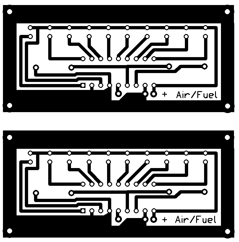
Foil Pattern, I made this pattern.  right mouse click, save as, and resize as you need to to fit.

This foil is on top with components, I wanted this so my board could be mounted from the front without worry about the back getting damaged.

This is the Parts Placement


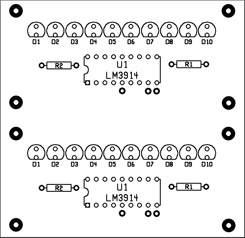
BILL OF MATERIALS        C:\Program Files\CIRCAD'98\airfuel2.pcb        07/21/00
--------------------------------------------------------------------------------
TYPE/VALUE    MODIFIER      PATTERN      QTY  COMPONENT REFERENCE IDENTIFICATION
--------------------------------------------------------------------------------
LED                         LED           20  D1    D1    D2    D2    D3    D3
                                              D4    D4    D5    D5    D6    D6
                                              D7    D7    D8    D8    D9    D9
                                              D10   D10
220ê          ¬W            R400P70        2  R2    R2
1Kê           ¬W            R400P70        2  R1    R1
LM3914                      DIP18          2  U1    U1
 
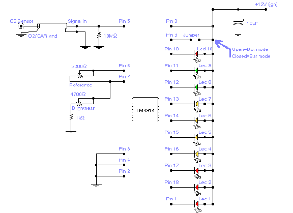
ADDITIONAL NOTES: Input is on Pin 5 from O2 Sensor, power is the + on the board,
 and the ground is the pad beside power that goes to the outside trace.


HomePage ] About ] Projects ] Fiero ] Dirt ] Sport ] Jet Ski ] Links ]